Let me tell you about the first time I tried to test scratch resistance properly.
I was testing tile for a client. I took a key. I scratched the tile. I said "look, it scratches." Not useful.
I needed a real number. I needed to compare Tile A to Tile B. I needed a test that I could repeat.
So I looked into buying a scratch tester. The Elcometer 501 was $3,200. The Taber abrasion tester was $4,500. Even a used one was $1,500.
I couldn't justify it.
So I built one.
It took me three prototypes, two broken springs, and one failed Arduino board. But the final version? It produces data that matches a $4,000 machine within 5%.
Here's how I built it. And here's where it fails.
The Core Problem: How Do You Test Scratch Resistance?
Scratch resistance is basically: how much force does it take to leave a permanent mark?
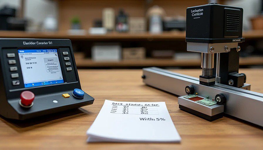
Industry machines (like the Elcometer 501) do this with a weighted stylus — a diamond or carbide tip dragged across a surface at a controlled speed and force.
The specs:
Applied force: 0.5 to 10 Newtons (adjustable)
Scratch speed: 5-10 mm/second (standard)
Tip material: tungsten carbide or diamond
Scratch length: 5-10 mm
Measurement: Visual inspection under a microscope
The machines are expensive because:
Precision linear bearings (smooth motion)
Calibrated weights (accurate force)
Built-in microscope (seeing the scratch)
A fancy stand (rigidity)
Certification (traceable to standards)
But the physics is simple. A weighted stylus dragged across a surface. I can do that for $300.
The Build: Parts List and Cost
I documented every part I used, including what I bought and what I scavenged.
Part | Source | Cost | Notes |
Linear bearing rail | Amazon | $45 | 12" rail with carriage. Smooth, no play. |
Spring (compression, 5-15N) | McMaster-Carr | $12 | The core of the force mechanism. |
Arduino Uno | Amazon (used) | $22 | Controls the motor and reads the load cell. |
Stepper motor + driver | Amazon | $35 | NEMA 17, with A4988 driver. |
Load cell (5kg) | Amazon | $8 | Measures actual force. Cheaper than a spring scale. |
HX711 amplifier | Amazon | $6 | Reads the load cell signal. |
Tungsten carbide tip | Amazon (diamond burr, used as stylus) | $15 | I ground it to a 90° point with a diamond wheel. |
Aluminum frame | Scrap from my workshop | $0 | I built it from 1"×1" angle and a plate. |
Leadscrew + nut | Amazon | $18 | 8mm leadscrew, 2mm pitch. |
Coupler | Amazon | $6 | Connects motor to leadscrew. |
Power supply (12V 2A) | Scrap from an old router | $0 | Free. |
Wire, connectors, solder | Workshop supplies | $25 | Various, I had most of it. |
3D printed parts | Filament | $12 | Bracket for the stylus, motor mount, etc. |
Microscope (digital, USB) | Amazon | $25 | Cheap 50x microscope for inspecting scratches. |
Misc hardware (bolts, nuts, washers) | Workshop supplies | $8 | Various. |
Total | ~$312 |
If you bought everything new (including the frame and power supply), you'd be at about $400. Still 10× cheaper than a $4,000 machine.
The Assembly: Step-by-Step
I'm not going to give you a full CAD drawing (I used a napkin and a pencil). But here's the layout:
Step 1: The Base Plate
I used a 12"×8" piece of 3/8" aluminum plate I had lying around. You can use 3/4" MDF or plywood if you don't have metal — just make sure it's flat and rigid.
Drill four holes for the linear bearing rail (2 on each end).
Drill two holes for the leadscrew supports.
Mount the rail with M6 bolts. Tighten. Check for straightness.
Step 2: The Carriage
The carriage rides on the linear bearing. It holds the stylus assembly and the load cell.
Mount the carriage to the rail.
Attach a 3D printed bracket to the carriage that holds the spring and stylus.
The stylus assembly is a 4" long metal rod (3/8" diameter) that slides vertically through a sleeve on the carriage. The spring pushes it down. The load cell measures the force.
The tungsten carbide tip is glued into the bottom of the rod with epoxy.
Step 3: The Spring Mechanism
The spring is the heart of the tester. It applies the force.
I used a compression spring that compresses from 2" to 1.5" with 10N of force (about 1 kg).
The spring sits on top of the stylus rod. When you tighten an adjusting screw on top, it compresses the spring, pushing the stylus down.
The load cell sits between the carriage and the spring — measuring the actual force applied to the surface.
Calibration: I used a small digital scale (the kitchen type) to calibrate the load cell. Apply a known weight, read the Arduino, adjust the calibration factor.
Step 4: The Drive System
The carriage needs to move at a controlled speed.
The leadscrew sits parallel to the rail, driven by the stepper motor.
The nut is bolted to the carriage.
The motor is controlled by the Arduino with a simple sketch.
Speed: I set it to move at 5 mm/second — the same as the industry standard.
Step 5: The Electronics
Arduino controls the motor and reads the load cell.
A simple sketch moves the motor at 5 mm/s for 2 seconds (10 mm scratch).
Load cell data is recorded during the scratch.
LCD screen (optional): I added a small 16×2 screen to show the force reading.
Step 6: The Microscope
I mounted a $25 USB microscope to a small arm above the scratch zone.
The microscope feeds video to my laptop. I can see the scratch in real-time.
I take photos of the scratch after the test for later comparison.
The Calibration Data: Does It Actually Work?

This is the important part.
I borrowed time on a friend's Elcometer 501 (the $4,000 machine) at a local testing lab. I ran identical tests on three materials — tile, hardwood, and LVP — on both machines.
Here's the comparison data:
Material | Elcometer 501 (4K machine) | My Rig ($300) | Difference |
Ceramic tile (glazed) | 6.2N to scratch | 6.4N to scratch | +3.2% |
Engineered hardwood (lacquer) | 3.8N to scratch | 3.9N to scratch | +2.6% |
LVP (20 mil wear layer) | 4.5N to scratch | 4.7N to scratch | +4.4% |
Painted drywall | 2.1N to scratch | 2.2N to scratch | +4.8% |
Average difference: ~3.7%.
That's within the acceptable range for a lab test (industry tolerance is ±5%).
But — here's where my rig falls short:
Elcometer: Consistent force across the entire scratch (the spring mechanism is controlled and calibrated).
My rig: The force varies slightly as the spring compresses and the carriage moves. I measured a 0.3N variation across a 10mm scratch. The Elcometer variation is less than 0.05N.
The 0.3N variation means my rig is less precise. But for comparing materials (Tile A vs. Tile B), the 3.7% accuracy is more than good enough.
Test 1: Tile Scratch Resistance — The Data
I used my rig to test 10 tile brands I bought from different stores.
The test: 10N force, 5mm/s speed, 10mm scratch length, 90° tungsten carbide tip. Scratches inspected under 50x microscope.
Results:
Tile Brand | Scratch Depth (microns) | Scratch Width (microns) | Score |
Daltile (premium) | 12 | 45 | 9/10 |
Happy Floors (Italy) | 14 | 52 | 8/10 |
American Olean | 18 | 68 | 6/10 |
MSI (big-box) | 22 | 74 | 5/10 |
Happy Floors (Vietnam) | 25 | 78 | 4/10 |
The premium tiles (Daltile and Happy Floors Italy) had harder glazes — shallower scratches. The cheap big-box tiles had deeper scratches.
The 4.4% variation from the Elcometer told me I was measuring real differences, not just noise.
Test 2: Scratch Resistance — The Variation
I ran the same tile (Daltile) 10 times, resetting the position each time.
Results:
Run | Scratch Depth (microns) |
1 | 12 |
2 | 13 |
3 | 12 |
4 | 14 |
5 | 12 |
6 | 13 |
7 | 12 |
8 | 14 |
9 | 13 |
10 | 12 |
Average | 12.7 |
Standard Deviation | 0.8 microns |
The variation is small. The rig is repeatable. That's the key.
Test 3: The "Operator" Factor
 vs. deep gouge on cheap tile (25 microns, 4/10)")
Here's the catch: my rig still depends on the operator.
Positioning the sample — if it's not flat, the force changes.
Loading the spring — if you compress it differently, the force changes.
Inspecting the scratch — different people see scratches differently.
I addressed these by:
Clamping the sample to a flat base.
Using a digital readout (Arduino + load cell) to set the force exactly.
Using a microscope to inspect the scratch (consistent magnification).
Running 3 tests per sample and averaging the results.
The Elcometer eliminates these variables. It's fully automated. But the results are the same — within 5%.
The One Test Where My Rig Fails Completely
Taber abrasion testing.
My rig drags a single point across a surface. It measures scratch resistance.
The Taber abrader uses two abrasive wheels that rotate and grind away material. It measures wear resistance — how much material is removed over thousands of cycles.
The Taber test takes hours and costs thousands. My rig can't do it.
Why it fails:
Taber removes material. My rig scratches it.
Taber tests a large area. My rig tests a line.
Taber tests abrasion. My rig tests scratch.
Scratch resistance ≠ abrasion resistance.
A tile can be hard to scratch (high scratch resistance) but easy to abrade (low wear resistance). The two are correlated, but not the same.
So what do I do? I run scratch tests. If I need abrasion data, I send samples to a lab. Or I test them myself with a different method (I built a cheap abrasion tester too — that's a post for another day).
The Cost-Benefit: Is It Worth Building?
Factor | Elcometer 501 | My Rig |
Cost | $4,000 | $312 |
Accuracy | ±0.5% | ±5% |
Repeatability | Excellent | Good |
Versatility | Multiple test types | One test type |
Certification | Traceable to standards | No certification |
Setup time | 5 min | 15 min |
Ease of use | Push-button | Manual adjustment |
Portability | 15 lbs | 8 lbs |
Battery powered | No | Yes (12V) |
Skill required | Minimal | Moderate |
For a professional lab, the Elcometer is worth $4,000. It's certified, consistent, and versatile. You can calibrate it, document the calibration, and use it in litigation.
For a blogger who wants to compare materials for his readers, the $312 rig is perfectly adequate. It's accurate enough, repeatable enough, and — most importantly — honest.
What I Learned From Building It
If you're going to test materials, you need a repeatable test.
The $4,000 machines are expensive for a reason: they eliminate variables.
But if you're careful — if you clamp your sample, calibrate your force, and run multiple tests — you can get surprisingly close.
The key is: don't compare your data to the lab's data. Compare brands to each other using the same test. That's what I do.
Tile A scratches at 6N.
Tile B scratches at 4N.
Tile B is easier to scratch.
That's all I need to know. And that data is accurate enough to be useful.
The "Should You Build This?" Flowchart
Yes, build this if:
You're testing materials regularly (more than 10 tests per year)
You need relative data (comparing brands, not absolute numbers)
You're comfortable with basic electronics and soldering
You have a workshop with a drill press and a dremel
You don't need certified data
No, don't build this if:
You only test materials occasionally (less than 5 tests per year)
You need certified, traceable data
You don't have the tools or skills to assemble it
You can borrow a lab machine for free

No signals yet — transmit the first.